
Oscilloscope Guide
An oscilloscope is a device that can measure varying voltage signals and display them on a screen. Most oscilloscopes come with features that allow you to measure the input signal in various ways, such as maximum voltage or time of voltage pulse. This page is intended to help you learn some of the basics about oscilloscopes, understanding PMT signals, and to help you test your PMTs. The oscilloscope model used in these pictures is a Tektronix TDS 2022 (200 MHz, 2GS/s), and yours may look a bit differently.Understanding the Interface
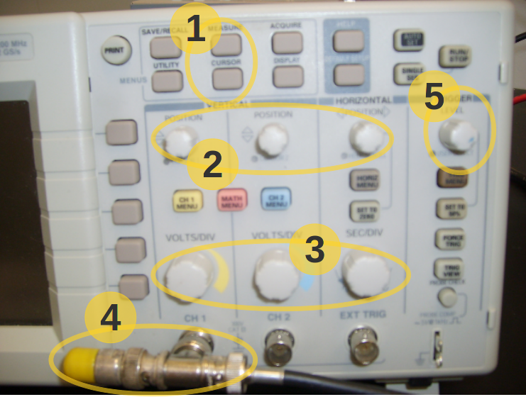 1 - Measure & Cursor buttons
Most oscilloscopes have some sort of button that allows you to display a cursor/dashed line and to allow to easily measure various parts of the display. Usually the cursor can be moved using the various knobs. In this model, the Measure tool can provide you with a frequency, max and min voltage values, and more. You may need to use the keys near the display to adjust options.
2 - Position knobs
Without any other selections, these knobs will simply move the display up, down, or side to side. With the Cursor tool, these knobs move the cursors.
3 - Scale knobs
These knobs change the scale of your display. You'll notice that your display is divided into a grid, where the horizontal axis is typically time and the vertical axis is usually voltage. Somewhere on the display there should be a reference to what scale your display is currently set to (i.e. 5ms/division or 100mV/division).
4 - Input
For CROP's PMTs, you will need a T-connector with a terminal resistor (as shown).
5 - Trigger level
The trigger basically refers to the point in which the oscilloscope records a signal, and you should notice a small arrow near the edge of the display which indicates the current trigger level. Try moving it up or down and notice the changes in the signal.
Understanding the Display
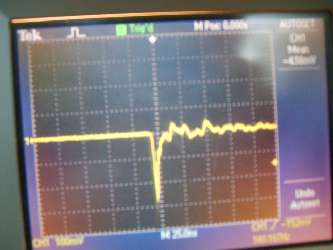 A "good" PMT will display a similar signal such as the one above. Note that the oscilloscope settings are at (100mV/div, 25ns/div) and the trigger level is set so the frequency of signals is around 100Hz. The sudden drop in voltage is caused by the capacitors inside the PMT becoming discharged. They discharge when an electrical pulse is created in the PMT as a result of a high energy particle striking the detector and briefly illuminating the internal scintillator.
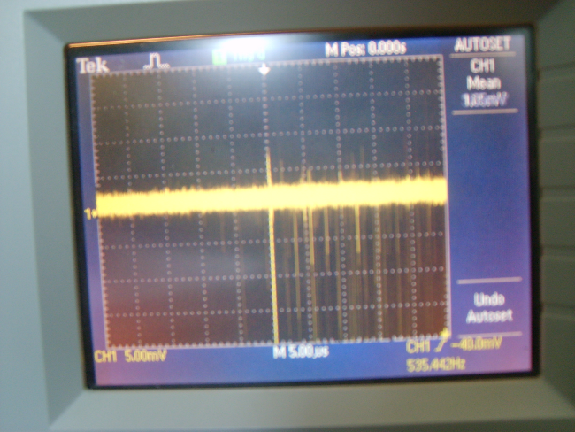 All PMTs will have noise associated with the electrical current powering it. A "good" PMT should have a small amount of noise, because strong noise could be accidentally detected as a cosmic ray strike. To see the noise band of a PMT, change the settings of the oscilloscope to (2mV/div, 5µs/div) and determine the thickness of the band using the Cursor tool. A PMT with a noise band around 1mV is usually pretty good.